UML Class Diagram

Unified Modeling Language (UML) is a visual modeling language that is widely used in software engineering to create diagrams that represent the software design. One of the most popular types of UML diagrams is the class diagram, which is used to represent the classes and relationships in an object-oriented programming system.
In this blog post, we will take a closer look at the UML class diagram, its components, and how to create one.
What is a UML Class Diagram?
A UML class diagram is a graphical representation of a system's classes, interfaces, and the relationships between them.
Purpose of UML Class Diagram
Some of the key purposes of UML diagrams include:
Visualization: UML diagrams provide a visual representation of a software system, which can make it easier to understand and communicate its structure and behavior.
Analysis and Design: UML diagrams can be used to analyze and design software systems by identifying their components, relationships, and behavior.
Communication: UML diagrams provide a common language and notation for communicating ideas and concepts related to software systems among team members and stakeholders.
Documentation: UML diagrams can be used to document software systems by capturing their structure, behavior, and relationships.
Implementation: UML diagrams can be used to guide the implementation of a software system by providing a blueprint for its components and behavior.
Components of a UML Class Diagram
A UML class diagram consists of several components, including:
Class: A class is a blueprint for creating objects that have similar attributes and behaviors. In a class diagram, a class is represented as a rectangle with the class name at the top.
Attributes: An attribute is a characteristic of a class, such as its name, age, or address. In a class diagram, attributes are listed below the class name.
Methods: A method is a function that a class can perform. In a class diagram, methods are also listed below the class name after attributes.
Relationships: Relationships describe how classes are related to each other. There are several types of relationships, including inheritance, association, aggregation, and composition. In a class diagram, relationships are represented as lines connecting the classes.
UML Class Notation

The name of the class appears in the first partition.
Attributes are shown in the second partition.
Operations(Methods) are shown in the third partition.
Static members (attributes or operations) are always underlined
Abstract Classes or Interfaces are denoted by <<ClassName>> or written in Italics
The attribute type is shown after the colon.
The return type of a method is shown after the colon at the end of the method signature.
The return type of method parameters is shown after the colon following the parameter name.
The +, -, and # symbols before an attribute and operation name in a class denote the visibility of the attribute and operation.
Public (+) Private (-) Protected (#)
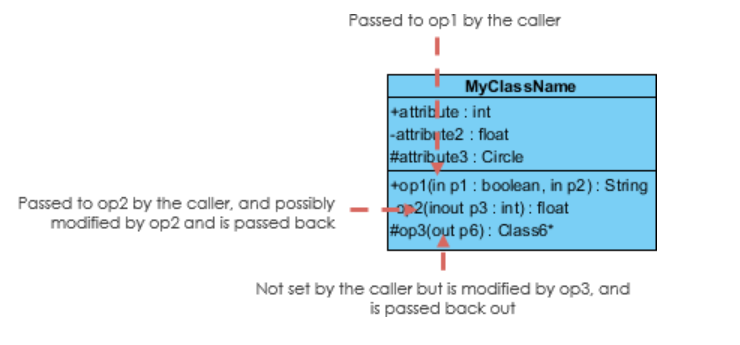
- Each parameter in an operation (method) may be denoted as in, out or inout which specifies its direction with respect to the caller. This directionality is shown before the parameter name.
Types of Relationships in UML Class Diagrams
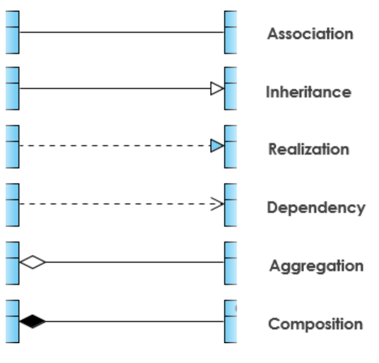
Inheritance(Generalization):
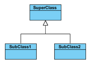
Inheritance is a relationship between two classes where one class (the subclass) inherits the properties and methods of another class (the superclass).
Represents an "is-a" relationship.
In a class diagram, inheritance is represented by an arrow pointing from the subclass to the superclass.
SubClass1 and SubClass2 are specializations of SuperClass
SuperClass is the generalization of SubClass1 and SubClass2
Association:
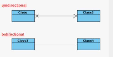
The association is a relationship between two classes where one class uses another class.
Bidirectional Association- Class3 can use Class4 and Class4 can also use Class3
Unidirectional Association- Only Class1 can use Class2 but not vice-versa
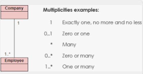
You can set the multiplicity value on each end of an association between classifiers to show the number of objects that can participate in the relationship.
Aggregation:
A special type of association.
It represents a "has-a" relationship.
Vehicle "has-a" Driver or Driver is "part-of" Vehicle
Objects of Vehicle and Driver have separate lifetimes.
Diamond is present at the association end, which is connected to the class that represents the aggregate.

Composition:
Composition is a stronger form of aggregation where one class is composed of another class and the contained class cannot exist without the container class.
A special type of aggregation where parts are destroyed when the whole is destroyed.
Objects of the Engine live and die with Vehicle. In other words, Engine cannot exist without vehicle.
if ClassA is "part-of" more than 1 class, it is definitely aggregation, not composition because then ClassA has an existence outside of any particular class.
Dependency:

Exists between two classes if changes to the definition of one may cause changes to the other (but not the other way around).
An object of one class might use an object of another class in the code of a method.
Realization:
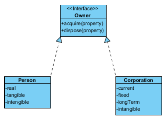
Realization is a relationship between the blueprint class and the object containing its respective implementation-level details.
This is the relationship between the interface and the implementing class.
Creating a UML Class Diagram
To create a UML class diagram, you can use various tools, including UML modeling software, such as Lucidchart, Visual Paradigm, or StarUML. The following steps outline the process of creating a UML class diagram:
Identify the classes and their attributes: Start by identifying the classes that will be included in the diagram and their attributes. You can use a table to list the classes and their attributes.
Determine the relationships: Once you have identified the classes, determine the relationships between them. You can use a table to list the relationships between the classes.
Draw the classes: Using your UML modeling software, start by drawing the classes as rectangles and adding their names and attributes.
Draw the relationships: Next, draw the relationships between the classes using lines and arrows. Be sure to label each relationship.
Add methods: Finally, add the methods of each class to the diagram.
Real World Example
Class Diagram for ATM

Conclusion
In conclusion, UML class diagrams are an essential aspect of the software development process, and mastering their notation is a valuable skill for any software developer or designer.
I hope this post has inspired you to continue exploring, learning, and creating in this exciting field.


